Mesh Refinement
REMORA allows both static and dynamic mesh refinement, as well as the choice of one-way or two-way coupling.
Note that any tagged region will be covered by one or more boxes. The user may specify the refinement criteria and/or region to be covered, but not the decomposition of the region into individual grids.
See the Gridding section of the AMReX documentation for details of how individual grids are created.
Static Mesh Refinement
For static refinement, we control the placement of grids by specifying the low and high extents (in physical space) of each box in the lateral directions. REMORA enforces that all refinement spans the entire vertical direction.
The following example demonstrates how to tag regions for static refinement. In this first example, all cells in the region \([0.15,0.25,\texttt{prob_lo_z}] \times [0.35,0.45,\texttt{prob_hi_z}]\) and in the region \([0.65,0.75,\texttt{prob_lo_z}]\times[0.85,0.95,\texttt{prob_hi_z}]\) are tagged for one level of refinement, where prob_lo_z and prob_hi_z are the vertical extents of the domain. They will be refined by a factor of 2 in the x and y directions, and not refined (i.e. refinement ratio 1) in the z direction. If needed, the refinement region will be expanded slightly to include the entirety of any partially-tagged coarse-level cell.
amr.max_level = 1
amr.ref_ratio = 2 2 1

remora.refinement_indicators = box1 box2

remora.box1.in_box_lo = .15 .25
remora.box1.in_box_hi = .35 .45

remora.box2.in_box_lo = .65 .75
remora.box2.in_box_hi = .85 .95
In the example below, we refine the region \([0.15,0.25,\texttt{prob_lo_z}]\times [0.35,0.45,\texttt{prob_hi_z}]\) by two levels of factor 3 refinement. In this case, the refined region at level 1 will be sufficient to enclose the refined region at level 2.
amr.max_level = 2
amr.ref_ratio = 3 3 1   9 9 1   #each triplet is refinement ratio in x,y,z for a single level

remora.refinement_indicators = box1

remora.box1.in_box_lo = .15 .25
remora.box1.in_box_hi = .35 .45
And in this final example, the region \([0.15,0.25,\texttt{prob_lo_z}]\times[0.35,0.45,\texttt{prob_hi_z}]\) will be refined by two levels of factor 3, but the larger region, \([0.05,0.05,\texttt{prob_lo_z}]\times [0.75,0.75,\texttt{prob_hi_z}]\) will be refined by a single factor 3 refinement.
amr.max_level = 2
amr.ref_ratio = 3 3 1   9 9 1

remora.refinement_indicators = box1 box2

remora.box1.in_box_lo = .15 .25
remora.box1.in_box_hi = .35 .45

remora.box2.in_box_lo = .05 .05
remora.box2.in_box_hi = .75 .75
remora.box2.max_level = 1
We note that instead of specifying the physical extent enclosed, we can instead specify the indices of
the bounding box of the refined region in the index space of that fine level.
To do this we use
in_box_lo_indices and in_box_hi_indices instead of in_box_lo and in_box_hi.
If we want to refine the inner region (spanning half the width in each direction) by one level of
factor 2 refinement, and the domain has 32x64x8 cells at level 0 covering the domain, then we would set
amr.max_level = 1
amr.ref_ratio = 2 2 2

remora.refinement_indicators = box1

remora.box1.in_box_lo_indices = 16 32  4
remora.box1.in_box_hi_indices = 47 95 11
remora.box1.max_level = 1
There is also an option to specify the indices of the bounding box of the refined region in the index space of the coarser level, using
in_box_lo_indices_crse and in_box_hi_indices_crse. This is useful when the user has a particular region in mind that they want to refine,
and they know the indices of that region on the coarser level but not on the finer level. In this case, the code will automatically adjust the
indices to create a valid box at the finer level.
amr.max_level = 1
amr.ref_ratio = 2 2 2

remora.refinement_indicators = box1

remora.box1.in_box_lo_indices_crse = 16 32  4
remora.box1.in_box_hi_indices_crse = 47 95 11
remora.box1.max_level = 1
The lo_indices should be divisible by the refinement ratio, and the hi_indices should be one less than a number divisible by the refinement ratio. There are no such requirements for the coarse level indices, since the code will adjust them as needed to create a valid box at the finer level.
Dynamic Mesh Refinement
Dynamically created tagging functions are based on runtime data specified in the inputs file. These dynamically generated functions test on either state variables or derived variables defined in REMORA_derive.cpp and included in the derive_list in Setup.cpp.
Available tests include
“greater_than”: \(\text{field} \geq \text{threshold}\)
“less_than”: \(\text{field} \leq \text{threshold}\)
“adjacent_difference_greater”: \(\text{max}( | \text{difference between any nearest-neighbor cell} | ) \geq \text{threshold}\)
The example below adds two user-named criteria:
hi_temp: cells with density greater than 10 on level 0, and greater than 20 on level 1 and higher;lo_vort: cells with relative vorticity less than 0 that are inside the region \([0.25,0.25,\texttt{prob_lo_z}]\times[0.75,0.75,\texttt{prob_hi_z}]\);scalardiff: cells having a difference in the scalar of 0.01 or more from that of any immediate neighbor.
The first will trigger up to AMR level 3 and the second to level 2. The second will be active only when the problem time is between 100 and 300 seconds.
Note that temp and scalar are the names of state variables and vorticity is a derived variable.
Valid field options for refinement are: scalar, temp, salt, x_velocity, y_velocity, z_velocity,
and vorticity.
remora.refinement_indicators = hi_temp scalardiff

remora.hi_temp.max_level = 3
remora.hi_temp.value_greater = 10. 20.
remora.hi_temp.field_name = temp

remora.scalardiff.max_level = 2
remora.scalardiff.adjacent_difference_greater = 0.01
remora.scalardiff.field_name = scalar
remora.scalardiff.start_time = 100
remora.scalardiff.end_time = 300

remora.lo_vort.max_level = 1
remora.lo_vort.value_less = 0
remora.lo_vort.field_name = vorticity
remora.lo_vort.in_box_lo = .25 .25
remora.lo_vort.in_box_hi = .75 .75
Coupling Types
REMORA supports one-way and two-way coupling between levels; this is a run-time input
remora.coupling_type = "OneWay" or "TwoWay"
By one-way coupling, we mean that between each pair of refinement levels, the coarse level communicates data to the fine level to serve as boundary conditions for the time advance of the fine solution. For cell-centered quantities, and face-baced normal momenta on the coarse-fine interface, the coarse data is conservatively interpolated to the fine level.
The interpolated data is utilized to specify ghost cell data (outside of the valid fine region).
By two-way coupling, we mean that in additional to interpolating data from the coarser level to supply boundary conditions for the fine regions, the fine level also communicates data back to the coarse level in two ways:
The fine cell-centered data are conservatively averaged onto the coarse mesh covered by fine mesh.
The fine momenta are conservatively averaged onto the coarse faces covered by fine mesh.
A “reflux” operation is performed for all cell-centered data; this updates values on the coarser level outside of regions covered by the finer level.
Advected quantities which are advanced in conservation form will lose conservation with one-way coupling. Two-way coupling ensures conservation of the advective contribution to all scalar updates but does not account for loss of conservation due to diffusive or source terms.
Filling Ghost Values
REMORA uses an operation called FillPatch to fill the ghost cells/faces for each grid of data.
The data is filled outside the valid region with a combination of three operations: interpolation
from coarser level, copy from same level, and enforcement of physical boundary conditions.
Interpolation from Coarser level
Interpolation is controlled by which interpolater we choose to use. The default is conservative interpolation for cell-centered quantities, and analogous for faces. These options are currently hard-coded in REMORA. The paradigm is that fine faces on a coarse-fine boundary are filled as Dirichlet boundary conditions from the coarser level; all faces outside the valid region are similarly filled, while fine faces inside the valid region are not over-written.
Copy from other grids at same level (includes periodic boundaries)
This is part of the FillPatch operation, but can also be applied independently,
e.g. by the call
mf.FillBoundary(geom[lev].periodicity());
would fill all the ghost cells/faces of the grids in MultiFab mf, including those
that occur at periodic boundaries.
In the FillPatch operation, FillBoundary always overrides any interpolated values, i.e. if
there is fine data available (except at coarse-fine boundary) we always use it.
Example
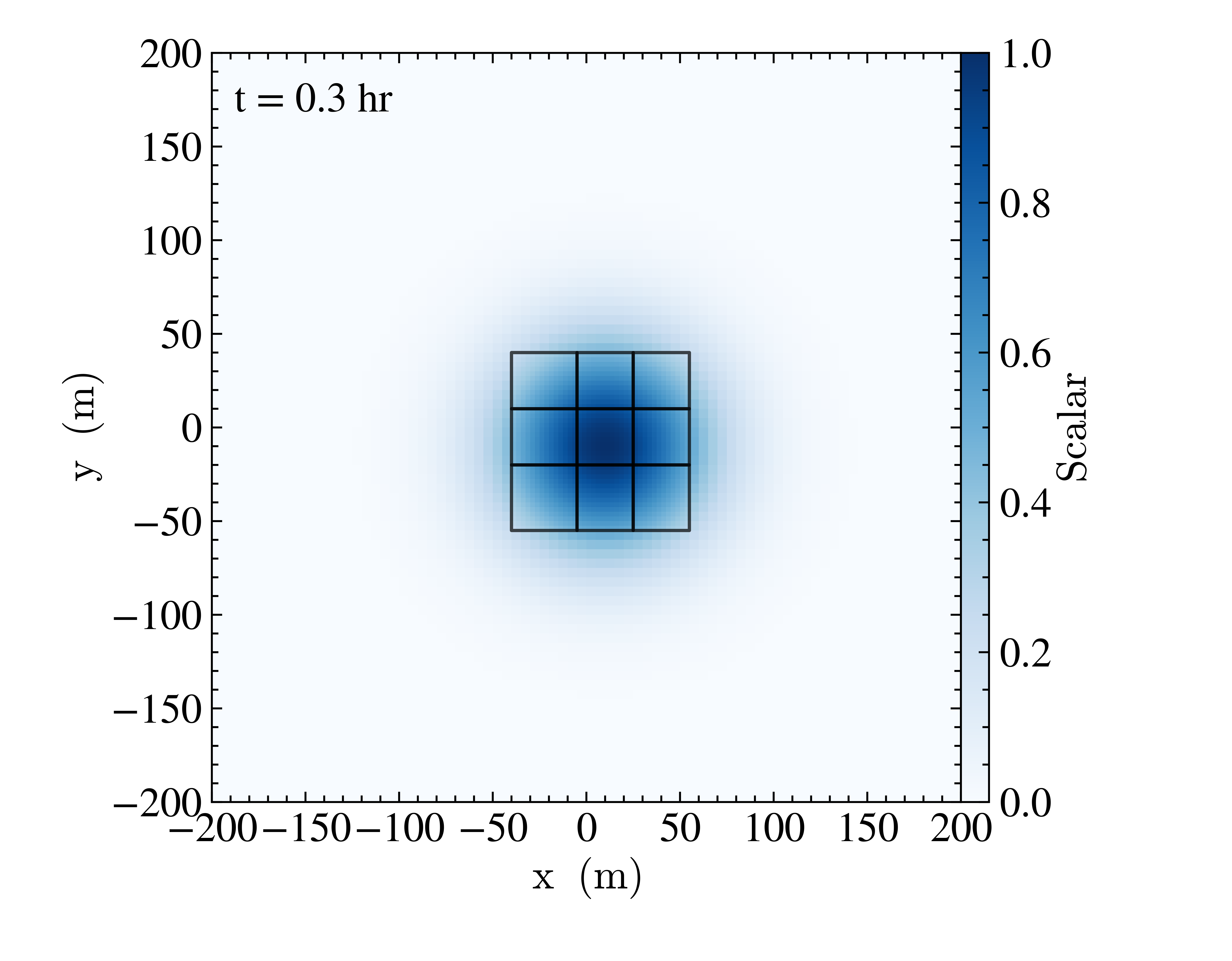
1 Mesh refinement example for scalar advection. The black lines show the higher-resolution grids.
The Advection problem simulates the advection of a Gaussian-distributed passive scalar. The example above was generated with the inputs file found in Exec/Advection/inputs_ml. The regions with scalar density greater than 0.5 are tagged for refinement after 200 seconds of evolution. In order to have the smaller level 1 refined grids shown above, it was run with the runtime parameter amr.max_grid_size=16 16 16.