Mesh Refinement
REMORA grid refinement is currently only in the horizontal coordinates; the vertical coordinate cannot be refined. Refinement ratios can be any positive integer, and can be different in different horizontal (grid) directions. Multiple levels of refinement are supported, allowing for increasingly finer grids in regions of interest.
Warning
Mesh refinement is experimental, and subcycling refined levels in time
(remora.do_substep = 1, the default) especially so. Multi-level answers are not yet
considered production quality. Check a refined run against a single-level one at the same
resolution before relying on it, and treat a result that only appears under refinement as
suspect until it does.
Any tagged region will be covered by one or more boxes. The user may specify the refinement criteria and/or region to be covered, but not the decomposition of individual grids. This means that the tagged regions represent the minimum area that will be refined.
Tagging criteria based on field variable values or derived quantities are
evaluated only in unmasked regions. One exception is a criterion keyed on
mask itself, which exists to find the coast. A region defined by a box
(typically used in static mesh refinement) is refined in full whether it is land
or water. See Masked Regions and Tagging for what “means something” amounts
to per field.
See the Gridding section of the AMReX documentation for details of how individual grids are created.
Static Mesh Refinement
For static refinement, we control the placement of grids by specifying the low and high extents (in physical space defined by x and y in the model grid) of each box in the lateral directions. There is no refinement in the vertical direction.
In the following example, two regions are tagged for static refinement. They will be refined by a factor of 2 in the x and y directions, and not refined (i.e. refinement ratio 1) in the z direction. If needed, the refinement region will be expanded slightly to include the entirety of any partially-tagged coarse-level cell; more on this below.
amr.max_level = 1                               # Specifies the max level possible in any refinement region
amr.ref_ratio_vect = 2 2 1                      # Note always use 'ref_ratio_vec', since z refinement is always 1

remora.refinement_indicators = box1 box2        # A list of refinement region names

remora.box1.in_box_lo = 20000 45000             # Lower limits on bounding box region (x, y), in meters
remora.box1.in_box_hi = 30000 70000             # Upper limits on bounding box region (x, y), in meters
remora.box1.max_level = 1                       # The maximum refinement level for this box

remora.box2.in_box_lo = 25000 60000             # Same for 'box2' refinement region
remora.box2.in_box_hi = 50000 80000
remora.box2.max_level = 1
Any single tagged region will be covered by one or more boxes. The user may
specify the refinement criteria and/or region to be covered, but not the
decomposition of the region into individual grids. Tagging criteria are ignored
in masked regions and on land-sea boundaries, but these regions may still be
refined in order to accommodate adjacent tagged regions. One way to think of
static refinement is a permanent adaptive refinement tag. See the Gridding
section of the AMReX documentation for details of how individual grids are
created, and how boxes are defined. Input variables associated with AMReX are
accepted in REMORA input files, e.g., amr.max_level = 1.
Refinement does not need to be uniform in each horizontal dimension, for example
amr.ref_ratio_vec = 2 7 1 is valid.
Multiple levels of refinement can be specified by setting amr.max_level to
be greater than 1. Additional vectors of refinement ratios need to be passed to
amr.ref_ratio_vect that specify the refinement for each additional level.
Refinement ratios are multiplicative, such that each refinement factor increases
the last refinement level, so that for
amr.max_level = 3
amr.ref_ratio_vec = 2 2 1   2 2 1   3 3 1
level 1 will be refined at 2x, and level 2 will be refined 4x, and level 3 by 12x.
Refinement can be specified by indices as well as dimensional units. This may be particularly useful when using a curvilinear grid, where the x- and y-dimensions do not necessarily align with the grid.
To specify refinement using level 0 indices use the _indices_crse appendix,
like
amr.max_level = 1
amr.ref_ratio_vect = 4 4 1

remora.refinement_indicators = box1

remora.box1.in_box_lo_indices_crse =  6 21
remora.box1.in_box_hi_indices_crse = 17 37
remora.box1.max_level = 1
However, one way to make sure refined regions also have refined masking and
bathymetry is to provide a grid with a resolution (everywhere) associated with
the highest refinement level; lower levels are coarsened. In this case, it makes
sense to reference the finest grid, which is done using the _indices
appendix.
The values specified in this case need special care. The .in_box_lo_indices
values must be divisible by the higheset refinement specified by
arm.ref_ratio. Since these are ‘inclusive’ values, the
.in_box_hi_indices are required to N * amr.ref_ratio - 1. For example,
amr.max_level = 2
amr.ref_ratio_vect = 2 2 1   3 3 1

remora.refinement_indicators = box1

remora.box1.in_box_lo_indices = 12 36
remora.box1.in_box_hi_indices = 23 59
remora.box1.max_level = 2
Dynamic Mesh Refinement
Dynamically created tagging functions are based on runtime data specified in the inputs file. These dynamically generated functions test on either state variables or derived variables defined in REMORA_derive.cpp.
Available tests include
value_greater: \(\text{field} \geq \text{threshold}\)value_less: \(\text{field} \leq \text{threshold}\)adjacent_difference_greater: \(\text{max}( | \text{difference between any nearest-neighbor cell} | ) \geq \text{threshold}\)
The example below adds three user-named criteria:
hi_temp: cells with temperature greater than 10 on level 0, and greater than 20 on level 1 and higher. Triggers up to AMR level 3;tempdiff: cells having a difference in temperature of 0.01 or more from that of any immediate neighbor. Triggers up to level 2, and only when the problem time is between 100 and 300 seconds;lo_vort: cells with relative vorticity less than 0, and separately the region \([0.25,0.25,\texttt{prob_lo_z}]\times[0.75,0.75,\texttt{prob_hi_z}]\).
amr.max_level = 3
amr.ref_ratio_vec = 2 2 1   3 3 1   2 2 1

remora.refinement_indicators = hi_temp tempdiff lo_vort

remora.hi_temp.max_level = 3
remora.hi_temp.value_greater = 10. 20.
remora.hi_temp.field_name = temp

remora.tempdiff.max_level = 2
remora.tempdiff.adjacent_difference_greater = 0.01
remora.tempdiff.field_name = temp
remora.tempdiff.start_time = 100
remora.tempdiff.end_time = 300

remora.lo_vort.max_level = 1
remora.lo_vort.value_less = 0
remora.lo_vort.field_name = vorticity
remora.lo_vort.in_box_lo = 25000 60000          # This is not a limit on the refinement region, rather, it specifies
remora.lo_vort.in_box_hi = 50000 80000          # to refine the box AND apply the field test over the whole domain
The start_time and end_time of an indicator are in seconds since the
start of the run, that is, since remora.start_time, as in ERF. To give a
bound as a total time on the model clock instead – the clock
remora.start_time and remora.stop_time are on (see Reference date and calendar) –
use start_total_time or end_total_time. Each bound may be given in only
one of the two forms, but the two can be mixed: start_time with
end_total_time is allowed. With the default remora.start_time = 0 the
two forms coincide.
A window given as elapsed time moves with remora.start_time. A restart that
changes remora.start_time therefore shifts it on the model clock, by the
same amount the restart rebases the run’s elapsed time. Use the _total_time
forms for a window that should stay put across such a restart.
Here, temp is the name of a state variable and vorticity is a derived
variable. Valid field options for refinement are any cell-centered tracer this
run actually has, along with x_velocity, y_velocity, z_velocity,
vorticity, mask, bathymetry h, and, in a build with particles, <particle>_count.
Which tracers exist depends on the input: temp and salt always,
tracer and numbered tracer_1 and up only when remora.nscalar asks
for them (it defaults to 0), and biology names such as NO3 only with a
biology model. Naming a field that is not defined in the run aborts at setup
with the list of the ones it does. All but mask are restricted to water; see
Masked Regions and Tagging below for what that means field by field. Prefer
value_greater for a particle count: its ghost cells are left at zero rather
than filled, so adjacent_difference_greater on one sees a step at every grid
boundary and tags a set of cells that depends on the domain decomposition.
Masked Regions and Tagging
A field-based criterion – value_greater, value_less or
adjacent_difference_greater – on any field but mask is evaluated only
where the value it reads was computed from water alone, and
adjacent_difference_greater differences two wet-cell values only. This
mirrors how AMReX evaluates the same criteria in the presence of an embedded
boundary, where a covered cell is skipped and a difference is taken only across
a face the geometry leaves open.
Which cells that admits depends on where the field lives and how it is masked, so it is not simply “the wet cells”:
a tracer (
temp,salt,tracer, a biology tracer) is masked in place, so the test is just whether that cell is water;x_velocityandy_velocityare stored at a cell index but live on a face, and are masked bymsku(i,j) = mskr(i-1,j) * mskr(i,j)andmskv(i,j) = mskr(i,j-1) * mskr(i,j). A water cell whose neighbor across that face is land therefore holds an exact zero that is a mask artifact rather than stationary water, so both cells sharing the face must be water;vorticityis a centered difference of the cell-centered velocities that is not itself masked, so its value depends on the whole 3x3 block of cells around it and all nine must be water. This is a workaround for the derived field being unmasked and can be narrowed once it is not;z_velocityis tested on its own cell, but only because nothing currently writes it: the vertical velocity the model solves for is held in a temporary, so the plotted and taggablez_velocityis identically zero. If it is ever connected, its dependence will be the five-point cross, not its own cell.
A land cell is never tagged by any of these. The one field exempt from all of it
is mask, below.
Nothing else is untagged. A region named explicitly with
in_box_lo/in_box_hi (or the index-space forms) is refined in full, land
included, which is usually what is wanted when the region of interest straddles
a coast. Land may also end up refined because it is adjacent to a tagged region,
or because amr.n_error_buf grew one.
To refine the coastline deliberately, use mask as the field name. It is the
one field exempt from the rule above – a criterion keyed on the mask is asking
where the coast is, so it is evaluated on every cell. Since the mask is 0 or 1
exactly, adjacent_difference_greater = 0.5 on it tags every cell whose
neighbor differs, which is the water cells along the coast and the land cells
facing them, so the coast is refined from both sides.
remora.refinement_indicators = coast

remora.coast.max_level = 1
remora.coast.adjacent_difference_greater = 0.5
remora.coast.field_name = mask
How the mask itself is carried across levels, and how it weights the two-way average, is described in Land/Sea Masking.
Coupling Types
REMORA supports one-way and two-way coupling between levels; this is a run-time input
remora.coupling_type = "OneWay" or "TwoWay"
By one-way coupling, we mean that between each pair of refinement levels, the coarse level communicates data to the fine level to serve as boundary conditions for the time advance of the fine solution. For cell-centered quantities, and face-baced normal momenta on the coarse-fine interface, the coarse data is conservatively interpolated to the fine level.
The interpolated data is utilized to specify ghost cell data (outside of the valid fine region).
By two-way coupling, we mean that in additional to interpolating data from the coarser level to supply boundary conditions for the fine regions, the fine level also communicates data back to the coarse level in two ways:
The fine cell-centered data are conservatively averaged onto the coarse mesh covered by fine mesh.
The fine momenta are conservatively averaged onto the coarse faces covered by fine mesh.
A “reflux” operation is performed for all cell-centered data; this updates values on the coarser level outside of regions covered by the finer level.
Advected quantities which are advanced in conservation form will lose conservation with one-way coupling. Two-way coupling ensures conservation of the advective contribution to all scalar updates but does not account for loss of conservation due to diffusive or source terms.
Coarse-Fine Operators for the Barotropic Mode
The free surface and depth-averaged momentum cross a coarse-fine interface the way ROMS’s
nesting.F passes them between nested grids, not the way AMReX’s generic interpolators would.
The normal barotropic velocity on the fine side of an interface is set from the parent’s
fast-time-averaged mass flux per unit edge length, so the fine fluxes sum to the coarse one;
under two-way coupling the fine depth-averaged momentum is averaged back over ROMS’s nine-point
stencil with the interface faces themselves left out; and the free surface in the coarse-fine
ghost band is written to every leapfrog record at the child’s own sub-time. Each of these is a
runtime option, remora.cf_*, listed with its default and its cost under Mesh Refinement and
(Re)gridding in the Inputs section. The defaults match ROMS and are not exactly volume
conserving; the conservative setting is given there.
Filling Ghost Values
REMORA uses an operation called FillPatch to fill the ghost cells/faces for
each grid of data. The data is filled outside the valid region with a
combination of three operations: interpolation from coarser level, copy from
same level, and enforcement of physical boundary conditions.
Interpolation from Coarser level
Interpolation is controlled by which interpolater we choose to use. The default is conservative interpolation for cell-centered quantities, and analogous for faces. These options are currently hard-coded in REMORA. The paradigm is that fine faces on a coarse-fine boundary are filled as Dirichlet boundary conditions from the coarser level; all faces outside the valid region are similarly filled, while fine faces inside the valid region are not over-written.
Copy from other grids at same level (includes periodic boundaries)
This is part of the FillPatch operation, but can also be applied
independently, e.g. by the call
mf.FillBoundary(geom[lev].periodicity());
would fill all the ghost cells/faces of the grids in MultiFab mf, including
those that occur at periodic boundaries.
In the FillPatch operation, FillBoundary always overrides any
interpolated values, i.e. if there is fine data available (except at coarse-fine
boundary) we always use it.
Example
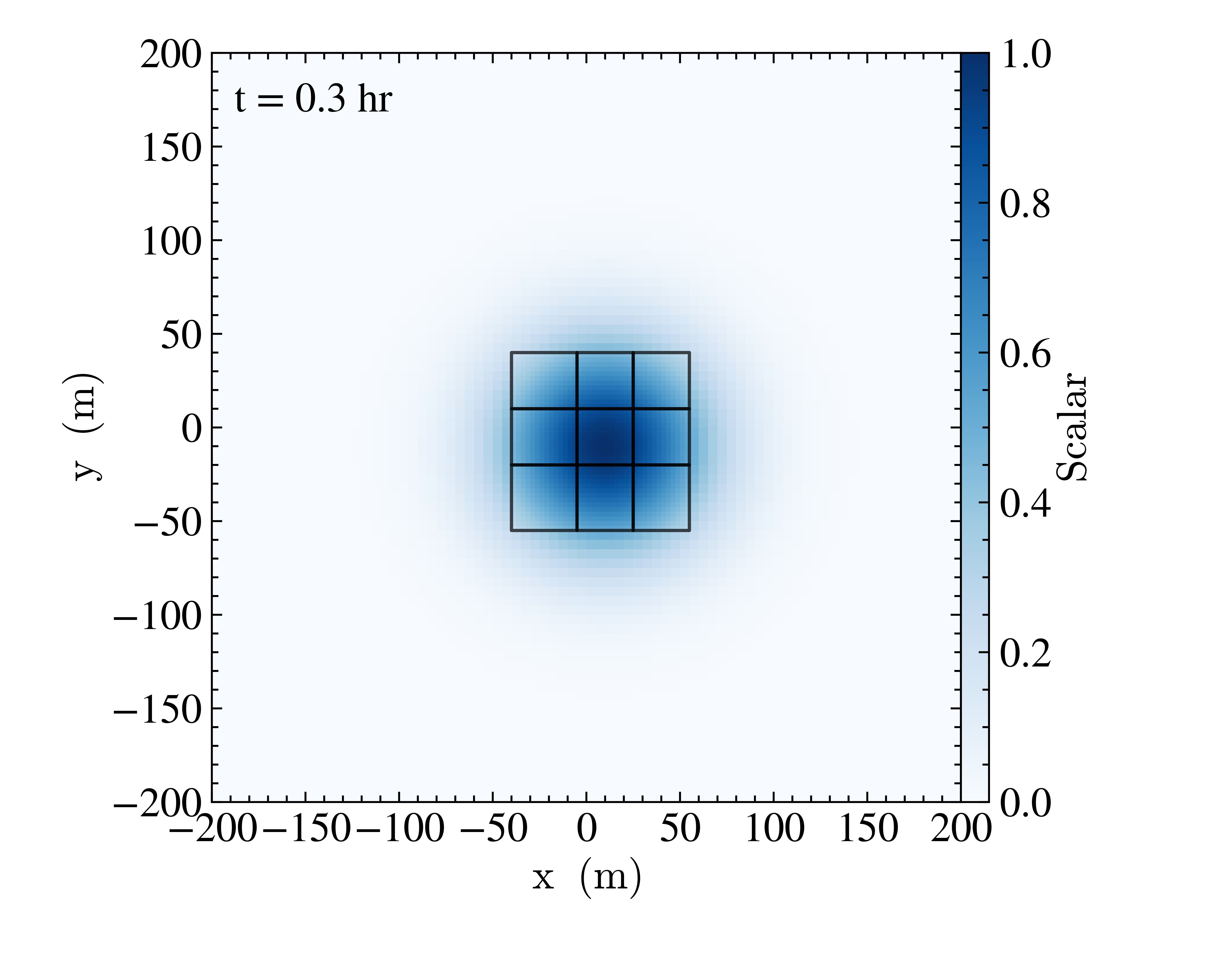
1 Mesh refinement example for scalar advection. The black lines show the higher-resolution grids.
The Advection problem simulates the advection of a Gaussian-distributed
passive scalar. The example above was generated with the inputs file found in
Exec/Advection/inputs_ml. The regions with scalar density greater than 0.5
are tagged for refinement after 200 seconds of evolution. In order to have the
smaller level 1 refined grids shown above, it was run with the runtime parameter
amr.max_grid_size=16 16 16.